 Omron FINS Integration Guide
Talk directly to Omron PLCs using MaestroHub's Omron FINS connector. This guide walks you through the connection settings, how to author each function type, what the returned data looks like, and how to use the corresponding nodes in the Pipeline Designer.
If you have never worked with an Omron PLC before, start with the short Background section — it explains the vocabulary used throughout the rest of this page (FINS, DM, CIO, routing triples, and so on).
Overview
With the Omron connector you gain:
- FINS/UDP support on port 9600 for CV, CS/CJ, CP, and NJ/NX series PLCs
- Typed memory reads for
Bit,Word,DWord,Real,Bytes, andStringacross the standard Omron memory areas (CIO, WR, HR, AR, DM, EM, TIM/CT, TASK_STATUS) - Batched multi-point reads — contiguous points in the same area are coalesced into a single FINS frame to minimise round-trips
- Typed writes of single values or contiguous runs
- Atomic bit control (Set / Reset / Toggle) via Force Set/Reset, which is safer than a full word rewrite
- Cheap PLC clock reads — also useful as a lightweight health check
- Automatic retries on transport-level failures, with configurable count and delay
- Dynamic parameters — every function field accepts
((parameterName))placeholders for use in pipelines
Background: what is FINS?
FINS (Factory Interface Network Service) is Omron's proprietary industrial protocol for PLC communication. This connector speaks FINS/UDP (port 9600), which is the most commonly enabled transport on Omron Ethernet units and built-in PLC Ethernet ports.
Every FINS message carries a six-field routing triple that identifies both endpoints on the FINS network:
- Destination (the PLC):
DNA(network number),DA1(node number),DA2(unit number) - Source (this client):
SNA,SA1,SA2
On a single flat local network you typically leave all network numbers at 0, leave the destination node at 0 (MaestroHub derives it from the last octet of the PLC IP, which is the Omron convention), and pick a unique sourceNode for MaestroHub.
Omron memory is organised into named areas, each addressed in 16-bit words. The areas most people use day-to-day are:
| Area | Name | Typical use | Bit-addressable | Writable |
|---|---|---|---|---|
CIO | Core I/O | Physical I/O channels, internal relays | Yes | Yes |
WR | Work Area | General-purpose scratch memory | Yes | Yes |
HR | Holding Relay | Retentive across power cycles | Yes | Yes |
AR | Auxiliary Relay | System flags | Yes | 0..447 read-only; 448+ writable |
DM | Data Memory | Primary data area — setpoints, measurements | Yes | Yes |
EM | Expansion Memory | Additional data — requires a bank (0..12) | Yes | Yes |
TIM_CT_PV | Timer/Counter present value | Current timer/counter values (word only) | No | Yes |
TIM_CT_FLAG | Timer/Counter completion flag | Completion status (bit only) | Yes | No (read-only) |
TASK_STATUS | Task status | Task state flags (word only) | No | No (read-only) |
When referring to a bit inside a word, the Omron convention is area address.bit — for example CIO 100.3 means bit 3 of word 100 in the CIO area.
Connection Configuration
Creating an Omron Connection
Navigate to Connections → New Connection → Omron FINS and configure the PLC endpoint. The form is organised into five tabs: Connection, Routing, Advanced, Functions, and Health.
1. Profile Information
| Field | Default | Description |
|---|---|---|
| Profile Name | — | A descriptive name for this connection profile (required, max 100 characters). Must be unique across all connections. |
| Description | — | Optional description for this Omron connection |
| Labels | — | Key-value pairs to categorise this connection (max 10 labels). Examples: line: line-1, area: packaging, model: cj2m. |
2. FINS/UDP Endpoint
| Field | Default | Description |
|---|---|---|
| PLC IP Address | — | IPv4 address of the target Omron PLC (e.g. 192.168.250.1) — required. Hostnames are not accepted. |
| FINS/UDP Port | 9600 | UDP port the PLC is listening on (1–65535). 9600 is Omron's default for FINS/UDP. |
FINS/UDP requires direct UDP connectivity to port 9600 on the PLC. There is no authentication at the protocol level — secure the network path with VLANs, firewall rules, or VPN tunnels. Most Omron Ethernet units enable FINS/UDP out of the box; if you cannot reach the PLC, check that FINS/UDP is enabled in CX-Programmer / Sysmac Studio and that no switch / firewall is dropping UDP 9600.
3. FINS Routing
The routing triple identifies where the FINS request is going and who is sending it. For a single PLC on a flat local network, the defaults almost always work — leave Destination Node at 0 and set a unique Source Node.
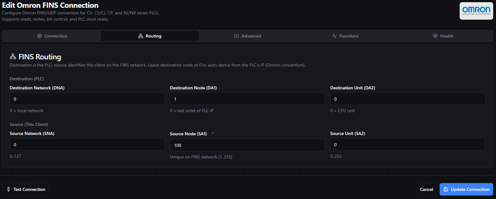
The Routing tab exposes the destination and source triples. For flat local networks the defaults are usually correct.
3a. Destination (the PLC)
| Field | Default | Range | Description |
|---|---|---|---|
| Destination Network (DNA) | 0 | 0–127 | Destination FINS network number. 0 means "local network" — the common case for a single-switch/VLAN setup. |
| Destination Node (DA1) | 0 | 0–255 | Destination FINS node. 0 auto-derives from the last octet of the PLC IP address (Omron convention). Override only if the PLC's FINS node number has been manually configured to something other than its IP suffix. |
| Destination Unit (DA2) | 0 | 0–255 | Destination FINS unit. 0 targets the CPU unit (the normal choice). Override to address a specific CPU Bus Unit. |
3b. Source (this client)
| Field | Default | Range | Description |
|---|---|---|---|
| Source Network (SNA) | 0 | 0–127 | Source FINS network number. Leave 0 on flat local networks. |
| Source Node (SA1) | 100 | 1–255 | Source FINS node — must be unique on the FINS network. Pick any number that is not already used by another FINS device (PLCs, HMIs, or other clients). A common convention is a "high" number (e.g. 100, 200) that humans won't accidentally reuse. |
| Source Unit (SA2) | 0 | 0–255 | Source FINS unit. 0 is correct for software clients like MaestroHub. |
If two FINS clients use the same Source Node on the same FINS network, replies will get delivered to whichever one happens to be listening — you'll see intermittent timeouts or corrupted data. When in doubt, give each MaestroHub instance a unique Source Node.
4. Advanced Settings
| Field | Default | Range | Description |
|---|---|---|---|
| Timeout (ms) | 2000 | 0–300000 | Per-request UDP response timeout. |
| Retries | 2 | 0–10 | Number of retries on transient (transport-level) failures. Protocol-level errors from the PLC are not retried. |
| Retry Delay (ms) | 250 | 0–60000 | Delay between retry attempts. |
| Byte Order | BigEndian | BigEndian / LittleEndian | Word-level byte order. Omron PLCs use BigEndian by default — leave this unless you have a specific reason to change it. |
| Local Bind Address | 0.0.0.0 | IPv4 or empty | Local IP interface to bind the outbound UDP socket to. 0.0.0.0 (all interfaces) is the normal choice. Pin to a specific NIC if the host is multi-homed and you need traffic to exit a particular interface. |
| Local Port | 9600 | 0–65535 | Local UDP port. 0 picks an ephemeral port. If the configured port is already in use, the connector automatically falls back to an ephemeral port. |
Only transport-level failures (UDP timeouts, socket closed, etc.) are retried. Protocol-level errors returned by the PLC — for instance "area not found" or "write protected" — surface immediately and are not retried.
Testing the Connection
Click Test Connection at the bottom of the form to verify connectivity before saving. The test performs a single Read Clock (FINS command 07 01) against the PLC — the cheapest possible FINS frame. A successful test proves:
- UDP path to the PLC is open on the configured port
- The routing triple is correct
- The PLC is powered and its FINS service is online
A failing test typically means a network/firewall issue, the wrong IP, or the wrong routing. The dialog shows the underlying error message.
Function Builder
Creating Omron Functions
Once the connection is saved:
- Open the connection and navigate to the Functions tab
- Click New Function to open the function type selection dialog
- Choose one of Read Memory Points, Write Memory, Bit Control, or Read PLC Clock
- Fill in the Basic tab (name, description, labels) and the Configuration tab (function-specific parameters)
- Use the Test button to validate the function before saving
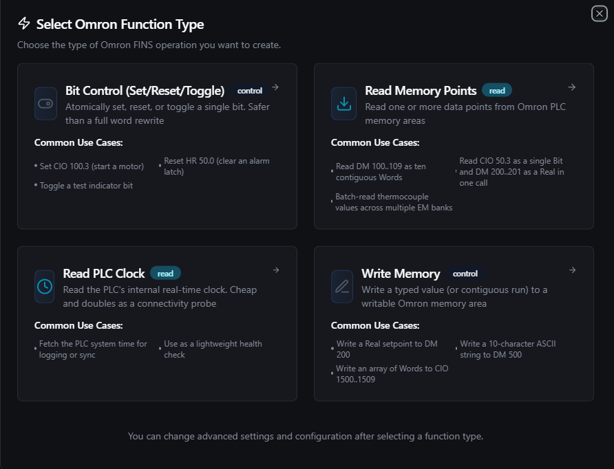
Pick a function type. Each type has its own configuration form — read/write/bit-control/clock.
Each function has two configuration tabs:
- Basic — Function name (required, max 100 characters, unique within the connection), optional description, and labels
- Configuration — Function-specific parameters (memory area, address, data type, values, etc.)
Data Types
Omron values are decoded/encoded according to a small set of typed tags. The Words on Wire column shows how many 16-bit words each unit occupies in a FINS frame — this determines how count multiplies.
| Data Type | Words on Wire | Value Shape | Description |
|---|---|---|---|
Bit | — (bit frame) | boolean | Single bit inside a word (requires bitOffset 0–15). Bit reads/writes use a different FINS frame (bit-addressed), so they are not merged with word reads. |
Word | 1 per unit | integer (0–65535) | Unsigned 16-bit word. |
DWord | 2 per unit | integer (0–4,294,967,295) | Unsigned 32-bit double word. Low word first, then high word — Omron's standard DWord layout. |
Real | 2 per unit | float (IEEE 754 single) | 32-bit floating point. Same low-word-first layout as DWord. |
Bytes | ⌈N/2⌉ words | single byte array | Raw byte buffer. The entire blob is treated as one value — the values array contains exactly one entry. |
String | ⌈N/2⌉ words | single string | ASCII string. Same blob semantics as Bytes; null-terminated on read. |
- For reads,
countis the number of units to read. Reading 5 consecutive DWords (count = 5) consumes 10 words on the wire. - For writes, the length of the
valuesarray implies the count. For Bytes/String,valuesmust have exactly one entry (the blob itself). - For bit reads,
countis the number of consecutive bits starting atbitOffset. A single-bit read setscount = 1.
Read Memory Points (omron.read)
Purpose: Read one or more typed data points from Omron PLC memory areas in a single call. The connector automatically coalesces contiguous same-area word points into a single FINS frame to minimise round-trips — if you read DM 100, DM 101, and DM 103 in the same request, that becomes one FINS read of DM 100..103.
Bit reads are not merged with word reads (they use a different FINS frame shape) and are issued one bit-point per frame.
Configuration Fields
| Field | Type | Required | Default | Description |
|---|---|---|---|---|
| Data Points | Array | Yes | 1 entry | List of data points to read (1 to 100). |
Data Point Fields
| Field | Type | Required | Default | Description |
|---|---|---|---|---|
| Name | String | Yes | dp1 | Unique key for this data point in the result. Must be unique across all points in the same read. |
| Memory Area | String | Yes | DM | Memory area: CIO, WR, HR, AR, DM, EM, TIM_CT_PV, TIM_CT_FLAG, or TASK_STATUS. TIM_CT_FLAG is bit-only; TIM_CT_PV and TASK_STATUS are word-only. |
| Address | Number | Yes | 0 | Starting word address (0–65535). |
| Data Type | String | Yes | Word | One of Bit, Word, DWord, Real, Bytes, or String. |
| Count | Number | No | 1 | Number of units to read (1–10000). For Bytes/String this is the length in bytes. |
| Bit Offset | Number | When dataType=Bit | 0 | Bit position within the word (0–15). |
| EM Bank | Number | When memoryArea=EM | 0 | Expansion Memory bank (0–12). |
Example request
{
  "dataPoints": [
    { "name": "zone_temp",    "memoryArea": "DM",  "address": 100, "dataType": "Real" },
    { "name": "setpoint",     "memoryArea": "DM",  "address": 102, "dataType": "Word" },
    { "name": "fan_running",  "memoryArea": "CIO", "address": 50,  "dataType": "Bit",  "bitOffset": 3 },
    { "name": "recipe_name",  "memoryArea": "DM",  "address": 500, "dataType": "String", "count": 20 }
  ]
}
Example result (under the data key of the function result)
{
  "results": {
    "zone_temp": {
      "values": [72.5],
      "dataType": "Real",
      "memoryArea": "DM",
      "address": 100,
      "count": 1
    },
    "setpoint": {
      "values": [1024],
      "dataType": "Word",
      "memoryArea": "DM",
      "address": 102,
      "count": 1
    },
    "fan_running": {
      "values": [true],
      "dataType": "Bit",
      "memoryArea": "CIO",
      "address": 50,
      "count": 1
    },
    "recipe_name": {
      "values": ["MIX_A1"],
      "dataType": "String",
      "memoryArea": "DM",
      "address": 500,
      "count": 20
    }
  }
}
Result Fields (per data point)
| Field | Type | Description |
|---|---|---|
values | Array | Decoded values. Always an array — for scalars like Word/Real it's a single-element array; for String/Bytes it's a one-entry array holding the full blob. |
dataType | String | Echoes the configured data type. |
memoryArea | String | Echoes the configured memory area. |
address | Number | Echoes the starting word address. |
count | Number | Echoes the configured count. |
If a single data point fails (e.g. a decode error or a per-point FINS end code), that point's entry contains an error field instead of values, category (error category), and optionally endCode (raw FINS end code). Other data points in the same request still succeed.
Use Cases: Poll process variables, batch-acquire recipe/setpoint data, monitor equipment state, read string labels and tags.
Write Memory (omron.write)
Purpose: Write a single value or a contiguous run of values to a writable Omron memory area. Writes to read-only areas (e.g. AR 0..447, TIM_CT_FLAG, TASK_STATUS) are rejected client-side before hitting the wire.
Configuration Fields
| Field | Type | Required | Default | Description |
|---|---|---|---|---|
| Memory Area | String | Yes | DM | Target writable area: CIO, WR, HR, AR, DM, EM, or TIM_CT_PV. |
| Address | Number | Yes | 0 | Starting word address (0–65535). |
| Data Type | String | Yes | Word | One of Bit, Word, DWord, Real, Bytes, or String. |
| Values | Array | Yes | [0] | Values to write. For scalar types the array length is the number of units (e.g. [10, 20, 30] writes three Words to three consecutive addresses). For Bytes/String the array must contain exactly one entry (the whole blob). Supports ((parameter)) placeholders. |
| Bit Offset | Number | When dataType=Bit | 0 | Bit position within the word (0–15). |
| EM Bank | Number | When memoryArea=EM | 0 | Expansion Memory bank (0–12). |
Example request — writing a Real setpoint to DM 200
{
  "memoryArea": "DM",
  "address": 200,
  "dataType": "Real",
  "values": [72.5]
}
Example request — writing a 10-character ASCII string to DM 500
{
  "memoryArea": "DM",
  "address": 500,
  "dataType": "String",
  "values": ["MIX_A1"]
}
Example request — writing three consecutive Words
{
  "memoryArea": "CIO",
  "address": 1500,
  "dataType": "Word",
  "values": [100, 200, 300]
}
Example result (under the data key of the function result)
{
  "memoryArea": "DM",
  "address": 200,
  "dataType": "Real",
  "written": 1,
  "timestamp": "2026-04-21T08:30:00Z"
}
Result Fields
| Field | Type | Description |
|---|---|---|
memoryArea | String | Echoes the target area. |
address | Number | Echoes the starting address. |
dataType | String | Echoes the data type. |
written | Number | Number of units written (length of the values array). |
timestamp | String | ISO 8601 / RFC 3339 UTC timestamp of the write. |
AR 0..447— reserved system flags. Writes are rejected;AR 448+is user-writable.TIM_CT_FLAG— completion flags are read-only.TASK_STATUS— read-only.TIM_CT_PV— writable, but does not support bit-level access.
Always double-check your address before writing to production equipment.
Use Cases: Push setpoints, download recipe/configuration values, write ASCII labels, bulk-update consecutive registers.
Bit Control (omron.bit.control)
Purpose: Atomically set, reset, or toggle a single bit in a bit-addressable memory area. This is safer than a Write with dataType=Bit because it uses Omron's Force Set/Reset FINS commands at the PLC — no other bits in the same word are touched.
Use Bit Control when you need to flip a single bit (a start/stop flag, an alarm latch, a test indicator) without worrying about what the rest of the word looks like.
Configuration Fields
| Field | Type | Required | Default | Description |
|---|---|---|---|---|
| Memory Area | String | Yes | CIO | Bit-addressable area: CIO, WR, HR, AR, DM, or EM. |
| Address | Number | Yes | 0 | Word address containing the bit (0–65535). |
| Bit Offset | Number | Yes | 0 | Bit position within the word (0–15). |
| Action | String | Yes | Set | One of Set, Reset, or Toggle. |
| EM Bank | Number | When memoryArea=EM | 0 | Expansion Memory bank (0–12). |
Example request — set motor-start bit CIO 100.3
{
  "memoryArea": "CIO",
  "address": 100,
  "bitOffset": 3,
  "action": "Set"
}
Example result (under the data key of the function result)
{
  "memoryArea": "CIO",
  "address": 100,
  "bitOffset": 3,
  "action": "Set",
  "timestamp": "2026-04-21T08:30:00Z"
}
Result Fields
| Field | Type | Description |
|---|---|---|
memoryArea | String | Echoes the target area. |
address | Number | Echoes the word address. |
bitOffset | Number | Echoes the bit position. |
action | String | Echoes the action (Set / Reset / Toggle). |
timestamp | String | ISO 8601 / RFC 3339 UTC timestamp of the operation. |
SetandResetare atomic at the PLC (Force Set/Reset commands).Toggleis implemented as read-modify-write (read word → flip bit → write word). If a second writer changes the same word between the read and the write, the toggle may clobber the other change. UseSet/Resetwhenever you can.
Use Cases: Start/stop motors, clear alarm latches, trigger test indicators, flip flag bits without disturbing neighbours.
Read PLC Clock (omron.read.clock)
Purpose: Read the PLC's internal real-time clock. It's the cheapest possible FINS frame and takes no parameters, which makes it handy as both a real-time-clock sync source and a lightweight connectivity probe.
Configuration Fields
This function has no configuration fields.
Example result (under the data key of the function result)
{
  "timestamp": "2026-04-21T08:30:42Z",
  "dayOfWeek": 2
}
Result Fields
| Field | Type | Description |
|---|---|---|
timestamp | String | PLC clock value as ISO 8601 / RFC 3339 UTC. |
dayOfWeek | Number | Day of week reported by the PLC (0 = Sunday, 1 = Monday, …, 6 = Saturday). |
Use Cases: Log PLC time, drift monitoring, use as a cheap health-check function in scheduled pipelines.
Using Parameters
Every write-side field in Omron functions accepts ((parameterName)) placeholders. This lets you bind values at pipeline runtime (e.g. from an upstream node or a trigger payload) instead of hard-coding them into the function config.
| Configuration | Description | Example |
|---|---|---|
| Type | Validate the expected value type | number, boolean, array, json, string |
| Required | Force critical inputs | Required / Optional |
| Default Value | Provide a safe fallback | 0, false, "MIX_A1" |
| Description | Document usage for other users | "Setpoint in °C", "Recipe name" |
Typical parameterised patterns:
values: [((setpoint))]— write a dynamic Real/Word setpointaddress: ((dmAddress))— target a DM address selected by an upstream nodeaction: ((bitAction))— decide Set vs Reset from a condition node
Testing Functions
Every Omron function can be tested before saving using the built-in Test dialog:
- Click the Test button in the function form
- The dialog shows an Execution Overview with the current configuration
- Override any parameter values in the Test Parameters section (for parameterised functions)
- Click Execute Test to run the function against the live PLC
- View the JSON response, including execution duration and timestamp
Pipeline Integration
Use the Omron functions you configure here as nodes inside the Pipeline Designer. Each function type exposes a matching node (connected.omron.read, connected.omron.write, connected.omron.bit.control, connected.omron.read.clock). Drag a node onto the canvas, bind it to the connection, select the function, and wire parameters from upstream outputs or constants.
For node-level details (full parameter reference, input/output schema, execution settings), see the Omron Nodes page.

Omron Read node with connection binding and parameter configuration
Common Use Cases
Production Data Acquisition
Poll DM and CIO for production counts, cycle times, temperatures, and setpoints with a single Read Memory Points function, then forward the result to a historian, MQTT topic, or SQL database.
Supervisory Control
Validate operator inputs and write them back as setpoints (via Write Memory) or mode changes (via Bit Control) in response to business rules, approvals, or scheduled triggers.
Recipe / Configuration Download
Parameterise a Write Memory function with an ((array)) placeholder and push entire recipe blocks (arrays of Words/DWords/Reals) to DM in a single call.
Maintenance & Diagnostics
Expose alarm latches, AR system flags, timer/counter present values, and the PLC clock to dashboards and alerting pipelines. Bit Control makes it easy to clear an alarm latch in response to an operator acknowledgement.
Troubleshooting
Connection Issues
| Symptom | Possible Cause | Solution |
|---|---|---|
| Connect fails with "failed to verify PLC connectivity" | PLC unreachable or FINS/UDP not enabled | Ping the PLC; verify port 9600 is open end-to-end; check FINS service is enabled in CX-Programmer / Sysmac Studio. |
| Must be a valid IPv4 address | Hostname entered instead of an IP | Hostnames are not accepted — enter the dotted-quad IPv4 (e.g. 192.168.250.1). |
| Intermittent timeouts / garbled replies | Duplicate Source Node on the FINS network | Pick a unique Source Node (SA1) for each MaestroHub instance. |
| "bind: address already in use" on connect | Local port already bound (e.g. a second Omron connection) | Leave Local Port at 9600 — the connector automatically falls back to an ephemeral port if the configured one is busy. |
| Routing works from a test tool but not MaestroHub | Wrong Destination Node | Leave DA1 at 0 to auto-derive from the PLC's IP, or enter the explicit FINS node configured on the PLC. |
Function Issues
| Symptom | Possible Cause | Solution |
|---|---|---|
| "memoryArea is required and must be a known area" | Typo or unsupported area | Use one of the exact area labels listed in Background. |
| "emBank is required when memoryArea=EM" | EM chosen without a bank | Fill in the EM Bank field (0–12). Check the PLC hardware configuration for available banks. |
| "bitOffset is required when dataType=Bit" | Bit data type without an offset | Enter the bit position (0–15). 0 is a valid value. |
| Write fails with "write protected" | Writing to AR 0..447, TIM_CT_FLAG, or TASK_STATUS | These ranges are read-only. Use AR 448+ for user-writable auxiliary relays. |
| Per-point error in a multi-point read | Area not present on this PLC model, or a FINS end-code error | The failing point's entry contains an error field plus FINS endCode — other points still return normally. Verify the area/address on the PLC. |
| "frame too large" | Too many words in a single write | Break the write into multiple smaller writes (keep each well under ~992 words, the FINS frame ceiling). |
Every Omron function has a Test button. Always execute a test against the live PLC before wiring the function into a pipeline — it's the fastest way to catch wrong addresses, wrong data types, or routing mistakes.
Supported PLC Families
The connector has been validated against:
- CV series (legacy)
- CS / CJ series (CJ1M, CJ2M, CS1, CS1G, etc.)
- CP series (CP1H, CP1L, CP2E, etc.)
- NJ / NX series (NJ101, NJ301, NJ501, NX1P2, NX1P3, etc.)
Any PLC that exposes FINS/UDP on an Ethernet unit (built-in or add-on) should work. FINS/TCP is not yet supported — reach out if you need it.