 Mitsubishi MELSEC Integration Guide
Talk directly to Mitsubishi MELSEC PLCs using MaestroHub's MELSEC connector, which speaks SLMP (SeamLess Message Protocol, formerly MC Protocol) over Ethernet. This guide covers connection setup, the device addressing model, authoring read/write functions, symbolic tag maps, and how the matching nodes slot into the Pipeline Designer.
Overview
The MELSEC connector provides:
- Bit and word device access — read/write
X,Y,M,B,L,F(bit) andD,W,R,ZR(word) devices - Typed values — interpret raw words as
BIT,WORD,INT,DWORD,DINT,REAL,LREAL, orSTRING - Batch block reads — read many datapoints from a device range in the fewest SLMP requests, with automatic grouping and chunking
- Timer / counter current values — read
TNandCNpresent values - Symbolic tag mapping — map friendly names to device addresses, importable from CSV or JSON
- 3E and 4E binary frames over TCP — the universal baseline plus serialized request/response correlation
- Automatic reconnection — transparent teardown-and-reconnect with a configurable retry budget
The connector targets the MELSEC family over an Ethernet module (built-in or add-on) that speaks SLMP / MC Protocol 3E or 4E binary frames:
- MELSEC-Q / -L series — select PLC Series
Q_L - MELSEC iQ-R / iQ-L series — select PLC Series
iQ_R(extended addressing) - MELSEC iQ-F (FX5) — select PLC Series
Q_L
The connector uses binary frames over TCP. ASCII encoding and UDP transport are out of scope.
Connection Configuration
Creating a MELSEC Connection
Navigate to Connections → New Connection → Mitsubishi MELSEC and configure the form. The form is organized into six tabs: Connection, Tag Map, Advanced, Functions, Scaling, and Health. The Functions, Scaling, and Health tabs unlock after the connection is saved.
1. Profile Information
| Field | Default | Description |
|---|---|---|
| Profile Name | — | A descriptive name for this connection profile (required, max 100 characters). Must be unique across all connections. |
| Description | — | Optional description for this MELSEC connection |
| Labels | — | Key-value pairs to categorize and organize the connection (max 10 labels) |
Example Labels
environment: production— Deployment environmentline: line-1— Production lineplc-series: iQ-R— PLC seriesarea: packaging— Plant area
2. SLMP Connection Settings
| Field | Default | Description |
|---|---|---|
| PLC Address | — | PLC IP/hostname and SLMP port in host:port form (e.g. 192.168.1.10:5007) — required. The port is set per Ethernet module — there is no universal default. |
| Frame Type | 3E | SLMP frame format — 3E (universal baseline) or 4E (adds a serial number for request/response correlation on noisy links) |
| PLC Series | Q_L | Selects the subcommand family and addressing width — Q_L (MELSEC-Q/-L, iQ-F/FX5) or iQ_R (MELSEC iQ-R/iQ-L, extended addressing) |
| Network No. | 0 | SLMP request destination network number (0–239). 0 = own network |
| Station No. | 255 | SLMP request destination station number (0–255). 255 (0xFF) = own host |
SLMP has no universal default port — on real hardware it is configured per Ethernet module (common choices include 5007, but it is entirely site-specific). The PLC Address field is host:port; a bare host with no port is rejected by the form. Check the Ethernet module's parameter settings in GX Works for the actual port.
- Frame Type — Use
3Eunless you specifically need request/response correlation;4Eprepends a serial number that the connector echoes back to match responses to requests, which helps on links that reorder or duplicate packets. - PLC Series —
iQ_Ruses the iQ-R extended (2-byte) addressing and subcommand family;Q_Lcovers the classic MELSEC-Q/-L and the FX5 (iQ-F) line. Picking the wrong series usually surfaces as an end-code error on the first read.
3. Advanced — Timing & Retries
The Advanced tab tunes transport timing, the PLC watchdog, and the retry policy.
| Field | Default | Description |
|---|---|---|
| Request Timeout (ms) | 5000 | Per-request transport timeout (0–60,000 ms) |
| CPU Monitoring Timer (ms) | 4000 | SLMP monitoring timer (the CPU-side watchdog), encoded on the wire in 250 ms units (0–16,383,750 ms). 0 = wait forever. |
| Idle Timeout (ms) | 60000 | Close the connection after this idle period (0–1,800,000 ms) |
| Retries | 2 | Number of retries on a transport-level failure (0–10) |
| Retry Delay (ms) | 500 | Delay between retry attempts (0–60,000 ms) |
| Word Swap | false | Swap word order for 32-bit and float values. Only needed for the rare device whose multi-word values are mapped big-endian (high word first). |
On a transport error (socket closed, dial failure, timeout) the connector tears down the session and reconnects on the next attempt, within the configured Retries budget separated by Retry Delay. A PLC end code (the PLC answered with an error) is not retried — it is surfaced immediately as a failed result, because retrying a bad request would only repeat the same error.
4. Tag Map
The Tag Map tab attaches an optional symbolic tag list — see Symbolic Tag Map below. It is entirely optional; every operation can always reference a raw device address.
Testing the Connection
Click Test Connection at the bottom of the form. The probe dials the PLC and issues a 1-word read of SD0 (a benign diagnostic special register) as its health check, then reports a latency in milliseconds. A non-zero SLMP end code still counts as success — the PLC answered, so the wire is alive — only a transport failure fails the probe. Use this before saving to catch a wrong address, port, frame type, or series early.
If Test Connection succeeds but you suspect you are pointed at the wrong listener, check whether the device actually logged the request. A green banner with no corresponding activity on the PLC side almost always means the address resolves to a different host (a common trap when the backend runs in a container — see Troubleshooting).
Device Addressing
A device address is a device prefix followed by a device number, e.g. D100, M5, X1A, ZR65536. The connector supports the MELSEC "common set" of devices:
Supported Devices
| Prefix | Device | Access | Numbering | Writable |
|---|---|---|---|---|
X | Input relay | Bit | Hex | No (read-only) |
Y | Output relay | Bit | Hex | Yes |
M | Internal relay | Bit | Decimal | Yes |
L | Latch relay | Bit | Decimal | Yes |
F | Annunciator | Bit | Decimal | Yes |
B | Link relay | Bit | Hex | Yes |
SM | Special relay (diagnostic) | Bit | Decimal | No (read-only) |
D | Data register | Word | Decimal | Yes |
W | Link register | Word | Hex | Yes |
R | File register | Word | Decimal | Yes |
ZR | File register (serial) | Word | Decimal | Yes |
TN | Timer current value | Word | Decimal | No (read-only) |
CN | Counter current value | Word | Decimal | No (read-only) |
SD | Special register (diagnostic) | Word | Decimal | No (read-only) |
X, Y, B, W)For X, Y, B, and W, the device number is parsed as hexadecimal — this is the classic MELSEC footgun. X1A is device number 0x1A (= 26 decimal), and Y20 is 0x20 (= 32 decimal). Y32 would address a different device than Y20. All other devices (M, D, R, L, F, ZR, TN, CN, SM, SD) use decimal numbering. This matches GX Works addressing.
On
ZR: the connector follows the SLMP Reference Manual and GX Works, which classify theZRnumber as decimal. (Some third-party libraries treat it as hex — MaestroHub deliberately does not.)
Device Browser
Every Read/Write Device function form includes a Device Browser in the right sidebar to help you discover addresses:
- Supported Devices lists every device code with badges for bit/word access, hex/decimal numbering, and read-only status. Click a device to insert its prefix into the Device field.
- The search box filters the list.
- The refresh button re-fetches the list. This is a cheap internal operation (
melsec.list.devices) — it does not hit the PLC. - If you have configured a tag map, your tags appear at the top; clicking a tag inserts its name.
Supported Data Types
Each value is interpreted as a data type on top of the raw SLMP word/bit access. Multi-word numeric types span consecutive devices, little-word-first by default (honoring the Word Swap flag).
| Data Type | Words on Wire | Value Shape | Example |
|---|---|---|---|
BIT | — (bit access) | boolean | true / false |
WORD | 1 | unsigned 16-bit integer (0–65,535) | 1234 |
INT | 1 | signed 16-bit integer (−32,768 to 32,767) | -100 |
DWORD | 2 | unsigned 32-bit integer (0–4,294,967,295) | 70000 |
DINT | 2 | signed 32-bit integer (−2,147,483,648 to 2,147,483,647) | -70000 |
REAL | 2 | IEEE 754 single-precision float | 3.14 |
LREAL | 4 | IEEE 754 double-precision float | 3.141592653589793 |
STRING | ⌈length / 2⌉ | text, word-packed (2 chars per word, low byte first) | Hello |
For STRING, the String Length field controls how many words are written. The default length of 1 writes only one word = two characters. Always set String Length to the full character length of the string you intend to write (and use the same length when reading it back), or the value is silently truncated. A STRING of length 5 occupies ⌈5/2⌉ = 3 words; MELSEC strings are NUL-padded within the field and trimmed at the first NUL on read.
DWORD, DINT, REAL, and LREAL are written and read as a single multi-word batch (atomic per request, never split across requests). The default word order is low word first, which matches the overwhelming majority of MELSEC devices. If a 32-bit or float value reads back byte/word-swapped, toggle Word Swap — either connection-wide on the Advanced tab, or per-operation on the function form.
Symbolic Tag Map
The tag map lets functions reference a friendly name (e.g. LineSpeed) instead of a raw address (D100). It is optional — operations can always use raw device addresses.
Open the connection → Tag Map tab. Each tag maps a name to a device address, a data type, and optionally a string length and word-swap override:
| Field | Required | Description |
|---|---|---|
name | Yes | Friendly tag name. Must be unique within the connection — duplicates are rejected. |
device | Yes | Device address the tag resolves to (e.g. D100, X1A) |
dataType | Yes | One of BIT, WORD, INT, DWORD, DINT, REAL, LREAL, STRING |
length | No | Character length, for STRING tags |
wordSwap | No | Per-tag word-swap override for 32-bit/float tags |
Importing tags (CSV or JSON)
Paste tags into the Import box and click Import Tags. Two formats are accepted:
CSV — header name,device,dataType[,length,wordSwap]:
name,device,dataType,length
Line1.Speed,D2100,DINT
Line1.Estop,X1A,BIT
Line1.Recipe,D300,STRING,10
JSON — an array of tag objects:
[
  { "name": "Line1.Speed", "device": "D2100", "dataType": "DINT" },
  { "name": "Line1.Estop", "device": "X1A", "dataType": "BIT" }
]
Imported tags are merged into the existing list; tags whose name already exists are skipped (and the count of skipped duplicates is reported). Tag names must be unique within the connection.
Anywhere a function asks for a Device / Tag, you can type either a raw address (D100) or a tag name (LineSpeed). The connector resolves the tag to its underlying address, data type, length, and word-swap setting at execution time.
Function Builder
Creating MELSEC Functions
After the connection is saved:
- Open the connection and navigate to the Functions tab
- Click New Function to open the function type selection dialog
- Choose Read Device, Read Block (Multi), or Write Device
- Fill the Basic fields (name, description, labels) and the Configuration fields (operation-specific parameters)
- Use the Test Function button to validate the function against the live PLC before saving
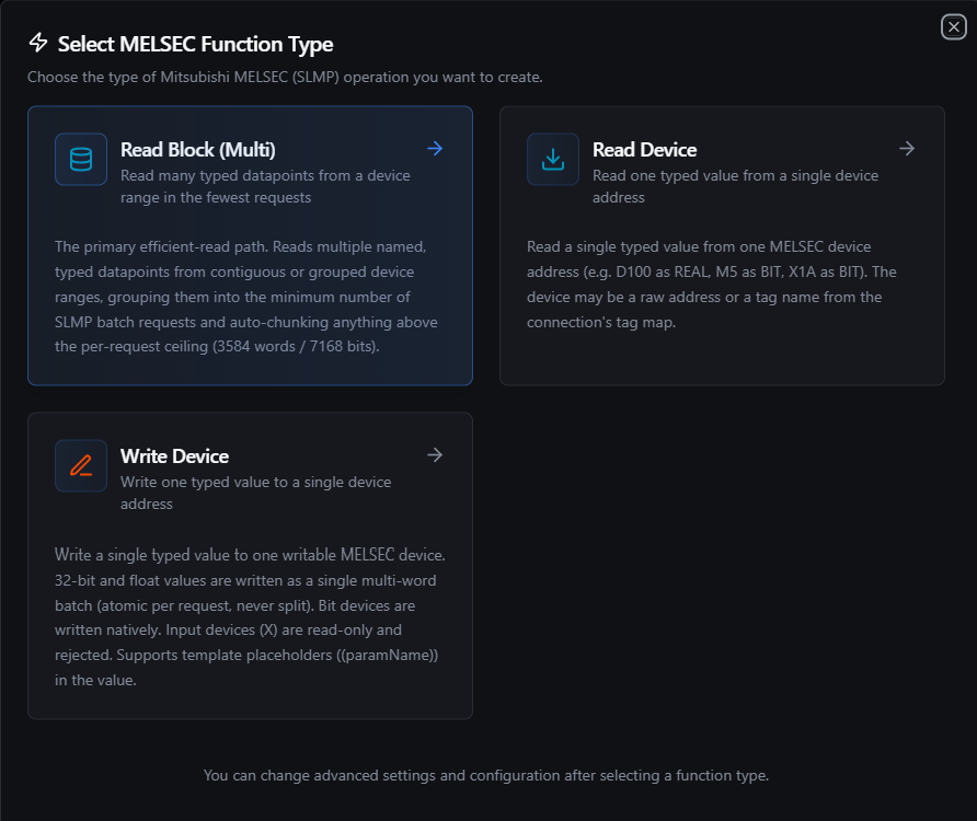
Pick one of three MELSEC function types: Read Device, Read Block, or Write Device
Read Device (melsec.read.device)
Purpose: Read a single typed value from one device address (e.g. D100 as REAL, M5 as BIT, X1A as BIT). The device may be a raw address or a tag name.
Configuration Fields
| Field | Type | Required | Default | Description |
|---|---|---|---|---|
| Device / Tag | String | Yes | — | Device address (D100, M5, X1A, ZR65536) or a tag name from the tag map |
| Data Type | Select | Yes | WORD | How to interpret the value (see Supported Data Types). Multi-word types read consecutive devices. |
| String Length | Number | No | 1 | Number of characters for STRING (word-packed, 2 chars per word). Ignored for other types. |
| Word Swap | Boolean | No | false | Override the connection word-swap setting for this read (32-bit/float only) |
Use Cases: Process variable monitoring, reading a setpoint, checking an input or status bit, polling a timer/counter current value.
Example Output
{
  "device": "D100",
  "dataType": "REAL",
  "value": 72.5
}
Read Block (Multi) (melsec.read.block)
Purpose: The primary efficient-read path. Reads multiple named, typed datapoints from contiguous or grouped device ranges, grouping them into the minimum number of SLMP batch requests and auto-chunking anything above the per-request ceiling (3584 words / 7168 bits per request).
Configuration Fields
| Field | Type | Required | Description |
|---|---|---|---|
| Data Points | Array | Yes | One or more datapoints to read in a single coalesced operation |
Each data point
| Field | Type | Required | Description |
|---|---|---|---|
name | String | Yes | Output key for this point in the result map (falls back to the device address if blank) |
device | String | Yes | Device address or tag name |
dataType | Select | Yes | BIT, WORD, INT, DWORD, DINT, REAL, LREAL, or STRING |
length | Number | No | Character length, for STRING points |
How grouping works: datapoints are sorted per device code and merged into runs. Adjacent word points within a small gap (up to 16 unrequested words) are coalesced into one ReadWords request; adjacent bit points within a 32-point gap are coalesced into one ReadBits request. Bit and word points use separate requests because they use different SLMP access modes. The totalReads field in the result tells you how many wire requests your points were coalesced into.
Use Cases: Dashboard snapshots, periodic historian logging, reading a block of mixed-type process values in one efficient call.
Example — Data Points
| name | device | dataType |
|---|---|---|
speed | D100 | WORD |
count | D102 | DINT |
level | D106 | REAL |
estop | X1A | BIT |
Example Output
{
  "count": 4,
  "values": {
    "speed": 1234,
    "count": 100000,
    "level": 72.5,
    "estop": true
  },
  "totalDataPoints": 4,
  "totalReads": 2
}
The three word points (
speed,count,level) coalesce into a singleReadWordsrequest and the one bit point (estop) into a singleReadBitsrequest —totalReads: 2for four datapoints. The decoded points are returned as a name-keyed map undervalues.
Write Device (melsec.write.device)
Purpose: Write a single typed value to one writable device. 32-bit and float values are written as a single multi-word batch (atomic per request, never split). Bit devices are written natively (no read-modify-write). Input devices (X) and other read-only devices are rejected.
Configuration Fields
| Field | Type | Required | Default | Description |
|---|---|---|---|---|
| Device / Tag | String | Yes | — | Writable device address (D100, M5, Y20) or a tag name. X (input) and other read-only devices are rejected. |
| Data Type | Select | Yes | WORD | How to encode the value (see Supported Data Types) |
| Value | Text | Yes | — | Value to write, parsed according to the data type. Supports ((paramName)) templates — see Using Parameters. |
| String Length | Number | No | 1 | Number of characters for STRING. Set this to the full string length (see the STRING warning above). Ignored for other types. |
| Word Swap | Boolean | No | false | Override the connection word-swap setting for this write (32-bit/float only) |
Value parsing by type
| Data Type | Accepted Value | Notes |
|---|---|---|
BIT | true, false, 1, 0, on, off, yes, no | Case-insensitive |
WORD | 1234, 0x04D2 | Unsigned 16-bit; hex accepted |
INT | -100 | Signed 16-bit |
DWORD / DINT | 70000, -70000 | 32-bit, written as 2 words |
REAL / LREAL | 3.14 | IEEE 754 float |
STRING | Hello | Word-packed; remember to set String Length |
Use Cases: Setpoint updates, recipe download, setting an internal relay or output bit, mode changes.
Example Output
{
  "device": "D100",
  "dataType": "REAL",
  "value": "3.14"
}
Always implement validation and safety checks before writing to industrial equipment. A setpoint, output bit, or recipe value can move a motor, valve, or actuator immediately. Gate writes behind a Condition node that bounds the value, or behind an explicit operator action.
Using Parameters
The Value field on Write Device supports parameter placeholders using ((parameterName)) syntax. Parameters are detected automatically from the field as you type and surface in the Function Parameters block. Use parameters to make a single function reusable across multiple pipeline contexts.
| Configuration | Description | Example |
|---|---|---|
| Type | Validate the expected value type | number, boolean, string |
| Required | Force critical inputs | Required / Optional |
| Default Value | Provide safe fallbacks for unattended runs | 0, false, 100.0 |
| Description | Document the parameter's purpose | "Target temperature setpoint in °C" |
Example
- Function type: Write Device
- Device:
D100 - Data Type:
REAL - Value:
((targetTemp))
At pipeline execution the runtime substitutes ((targetTemp)) with the value bound on the node and writes it to D100.
Testing Functions
Every Read Device, Read Block, and Write Device function can be tested before saving using the Test Function button:
- Click Test Function on the function form
- The dialog shows an execution overview with the resolved configuration
- If the function references
((paramName))templates, you are prompted for values - Click Execute Test to run the function against the live PLC
- The result — decoded value(s), any PLC end-code error, and execution timing — renders in the dialog
You do not need to save the function to test it.
Pipeline Integration
Use the MELSEC functions you configure here as nodes inside the Pipeline Designer. Reads and writes are exposed as matching connector nodes (connected.melsec.read, connected.melsec.write), and there is a dedicated MELSEC Read Group node (connected.melsec.readgroup) for executing several read functions in one node with request coalescing.
For node-level details (full parameter reference, input/output schema, execution settings), see the Mitsubishi MELSEC Nodes page.
- MELSEC Read — executes a single
melsec.read.deviceormelsec.read.blockfunction - MELSEC Write — executes a single
melsec.write.devicefunction - MELSEC Read Group — executes multiple read functions from one connection in a single node, coalescing their requests
For orchestration strategies that mix MELSEC with other data sources, see the Connector Nodes page.
Common Use Cases
Process Monitoring to a Historian or UNS
Author a Read Block function covering your line's key registers (speeds, counts, levels, status bits), drive it from a Schedule trigger, and route the decoded map to a historian, MQTT topic, or the Unified Namespace. The block read keeps the round-trip count low even for dozens of points.
Setpoint and Recipe Download
Receive setpoints from an upstream MES or operator UI, then issue parameterized Write Device functions (Value: ((setpoint))) to the relevant D registers. Validate every value with a Condition node before the write reaches the PLC.
Machine Control Bits
Set or clear internal relays (M) and outputs (Y) to start/stop equipment, acknowledge alarms, or toggle indicators — BIT writes go to the device natively without disturbing neighbouring bits.
Symbolic Tag Standardization
Build a tag map once (importing a CSV exported from your PLC documentation), then author every function against friendly names. Re-pointing a tag to a different register is a one-line change in the tag map rather than an edit to every function.
Troubleshooting
Connection Issues
| Symptom | Possible Cause | Solution |
|---|---|---|
Address must be in 'host:port' format | The PLC Address has no port | SLMP has no default port — add the Ethernet module's configured port, e.g. 192.168.1.10:5007. |
| Test Connection fails immediately (dial error / timeout) | Nothing listening on that host:port, or a firewall | Confirm the PLC IP and SLMP port (check the Ethernet module parameters in GX Works) and that the port is reachable from the connector host. |
| Test Connection succeeds but the PLC shows no activity | The address resolves to a different host | When the backend runs in a container, 127.0.0.1 points at the container, not your host — use the host's real IP or host.docker.internal. |
bad response subheader style error | A non-SLMP service is listening on that port, or a frame-type mismatch | Confirm the port belongs to the PLC's SLMP/MC service and that Frame Type matches the module configuration. |
Read / Write Issues
| Symptom | Possible Cause | Solution |
|---|---|---|
device X0 (X) is read-only | Tried to write an input or other read-only device | X, TN, CN, SD, SM are read-only. Write to a writable device (Y, M, D, …) instead. |
| Read of a hex device returns the wrong value | Forgot that X/Y/B/W numbers are hexadecimal | Y20 is 0x20 (32 decimal), not Y32. Re-check the address radix. |
STRING reads only the first 2 characters | String Length left at 1 on the read or the earlier write | Set String Length to the full character count on both the write and the read. |
| 32-bit / float value looks byte/word-swapped | Device maps multi-word values high-word-first | Toggle Word Swap (per-operation override, or connection-wide on the Advanced tab). |
| Reads succeed but values are unexpected after switching PLCs | Wrong PLC Series | iQ-R devices need PLC Series iQ_R; Q/L/FX5 need Q_L. A mismatch typically surfaces as an end-code error or wrong-length response. |
| Operation fails after the PLC was power-cycled | The session dropped | The connector tears down and reconnects on the next attempt within the Retries budget; a single operation may recover on its own, or retry once the PLC is back. |
Use the Test Function button on the connection page to validate every MELSEC function against the live PLC before wiring it into a pipeline. It is the fastest way to catch a wrong address, wrong radix (hex vs decimal), wrong data type, or a read-only target.