 Siemens S7 Integration Guide
MaestroHub integrates natively with Siemens S7 PLC families. Author reusable functions for deterministic reads and writes, manage security, and orchestrate PLC communication inside your pipelines.
Overview
The Siemens S7 connector provides:
- Direct communication over the S7 protocol through Maestro Agents or secure network tunnels
- Structured data access for Data Blocks, Inputs, Outputs, Markers, Timers, and Counters
- Type-aware conversions for BOOL, INT, DINT, REAL, STRING, and custom structures
- Session management with configurable rack/slot addressing and connection diagnostics
Connection Configuration
Creating a Siemens S7 Connection
Navigate to Connections → New Connection → Siemens S7 and configure the PLC endpoint with the following fields.
Siemens S7 Connection Creation Fields
1. Profile Information
| Field | Default | Description |
|---|---|---|
| Profile Name | - | A descriptive name for this connection profile (required, max 100 characters) |
| Description | - | Optional description for this S7 connection |
2. S7 Connection Settings
| Field | Default | Description |
|---|---|---|
| PLC Address | 192.168.1.100:102 | PLC IP address and port (format: host:port) – required, port must be 1-65535 |
| Rack | 0 | PLC rack number (0-7) – required |
| Slot | 1 | PLC slot number (0-31) – required |
| Connection Type | Programming Device (PG) | S7 connection mode – required |
Connection Type Options
| Connection Type | Value | Description | Typical Use Cases |
|---|---|---|---|
| Programming Device (PG) | 1 | For programming and diagnostics | PLC programming and diagnostics System monitoring and debugging Configuration and maintenance |
| Operator Panel (OP) | 2 | For operator panels and HMI | HMI and operator interfaces Data visualization panels Process monitoring applications |
| Basic Connection | 3 | Basic data exchange | Simple data exchange Basic communication needs Limited access scenarios |
3. Timeout Configuration
| Field | Default | Description |
|---|---|---|
| Request Timeout (ms) | 10000 | Maximum time to wait for S7 response (0-300000 ms, 0-5 minutes) |
| Idle Timeout (ms) | 30000 | Close connection after idle period (0-1800000 ms, 0-30 minutes, 0 = never) |
| Retry Count | 2 | Number of retries on communication failure (0-10) |
| Retry Delay (ms) | 1000 | Delay between retry attempts (0-60000 ms, 0-60 seconds) |
4. Security Configuration
| Field | Default | Description |
|---|---|---|
| Session Password | - | Optional password for protected PLCs (max 8 characters) |
5. Connection Labels
| Field | Default | Description |
|---|---|---|
| Labels | - | Key-value pairs to categorize and organize this S7 connection (max 10 labels) |
Example Labels
environment: production– Deployment environmentline: line-1– Production lineplc-type: s7-1200– PLC modellocation: factory-floor– Physical location
- Standard Port: The default S7 communication port is 102 (ISO-on-TCP).
- Rack and Slot: These values identify the CPU module location in the PLC rack (common combinations: rack = 0 with slot 1 or slot 2). Check your PLC hardware configuration for exact values.
- Connection Type Selection: PG provides full access for development/diagnostics, OP is tailored for HMIs, and Basic is for minimal data exchange.
- Password Protection: Only required if the PLC has password protection enabled in its security settings.
- Timeout Recommendations: Use a 10000 ms request timeout for local networks (increase for remote) and set idle timeout to 30000 ms or higher depending on application needs.
- Address Format: Must be
host:port. Host can be an IP address or hostname and port must be 1-65535 (102 is typical for S7). - Security Note: Session passwords are stored securely and used for establishing authenticated connections to protected PLCs.
Function Builder
Creating Siemens S7 Functions
Once the connection is saved:
- Go to Functions → New Function
- Choose S7 Read or S7 Write
- Select the Siemens S7 connection profile
- Define addresses, data types, and optional scaling/structure metadata
Author Siemens S7 read/write functions with address templates and data type mapping
Quick Add: Bulk Function Creation
For situations requiring multiple S7 functions to be created efficiently, the Quick Add feature enables batch creation through an interactive table or CSV import.
When to Use Quick Add
- Commissioning a new S7 PLC with numerous data blocks and memory areas
- Migrating tag databases from TIA Portal or other engineering tools
- Setting up standardized data acquisition across multiple PLCs
- Quickly establishing connectivity for testing and validation
How to Use Quick Add
- Navigate to your Siemens S7 connection in Connections
- Click Quick Add Functions button
- Choose your input method:
- Table Entry: Add function definitions row by row
- CSV Import: Upload a CSV file with PLC addresses and data types
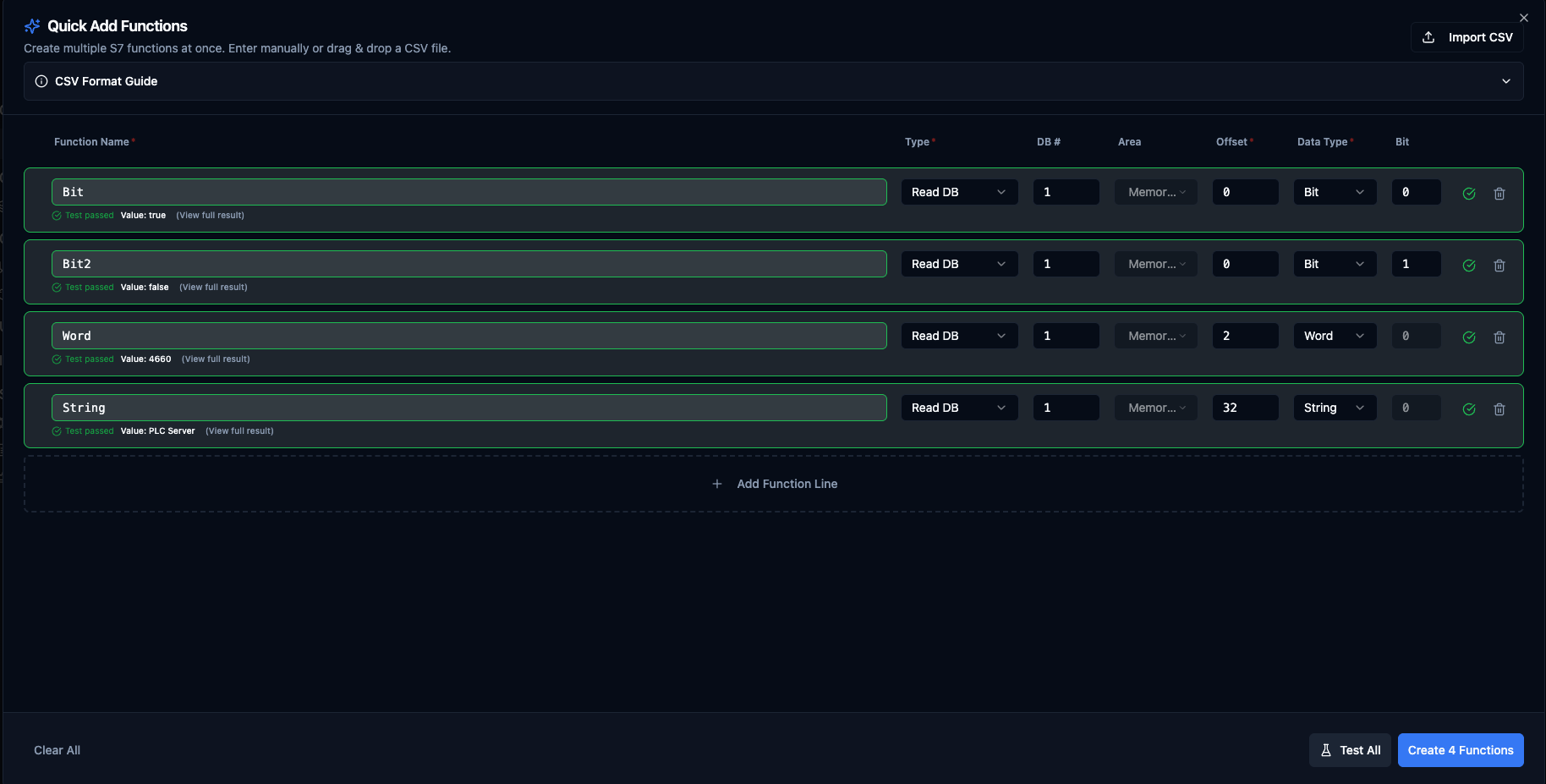
Quick Add Functions dialog for Siemens S7 with table entry and CSV import options
Table Columns
| Column | Description | Example |
|---|---|---|
| Function Name | The function the row belongs to. Rows sharing this name + Type + DB/Area collapse into one multi-point read function. | MotorTemps |
| Point Name | Name of this data point inside the function (reads only). Leave blank to auto-generate point1, point2, ... | temperature |
| Type | S7 operation type | Read DB, Write DB, Read Memory, Write Memory |
| DB # | Data block number (DB operations only) | 100 |
| Area | Memory area (Memory operations only) | I (Input), Q (Output), M (Memory) |
| Offset | Byte offset within DB or memory area | 10 |
| Data Type | S7 data type | REAL, INT, DINT, BIT, STRING |
| Size (bytes) | Auto-computed for fixed-size types; editable for STRING / WSTRING | 256 |
| Bit | Bit position (BIT data type only) | 0-7 |
| Value | Value to write (writes only). Accepts literals or ((paramName)) parameter templates. | 1500, ((targetRpm)) |
| Labels | Optional, all rows. Per-function tags for filtering and grouping. Click the Labels button to edit; the badge shows the current count. In CSV use key=value;key=value. Up to 10 labels per function. In grouped reads, labels merge across rows. | area=motors;team=automation |
Automatic Grouping
Rows that share the same Function Name + Type + DB number (or Area for memory reads) are merged into one multi-point read function. To create separate functions, give each row a distinct Function Name. Write functions are always one row = one function (writes never group).
Example:
| Function Name | Point Name | Type | DB # | Offset | Data Type | Result |
|---|---|---|---|---|---|---|
MotorTemps | temperature | Read DB | 1 | 10 | REAL | → merged into one MotorTemps function with two data points |
MotorTemps | pressure | Read DB | 1 | 14 | REAL | |
DeviceName | name | Read DB | 1 | 22 | STRING | → separate function with one data point |
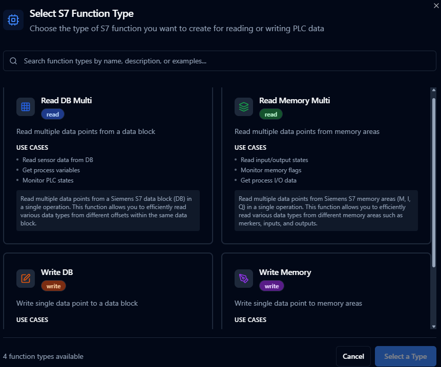
Supported Function Types
- Read DB (
s7.read.db.multi): Read multiple data points from a Data Block in one round-trip - Read Memory (
s7.read.memory.multi): Read multiple data points from memory areas I, Q, M in one round-trip - Write DB (
s7.write.db): Write a single value to a Data Block - Write Memory (
s7.write.memory): Write a single value to memory area Q or M (writes to Process InputsIare not permitted)
Data Type Options
Reads accept any S7 data type. Writes are restricted to the types the backend can serialise:
| Data Type | Bytes | Read | Write to DB | Write to Memory |
|---|---|---|---|---|
BIT | 1 (bit position 0-7) | ✓ | ✓ | ✓ |
BYTE | 1 | ✓ | ✓ | ✓ |
WORD | 2 | ✓ | ✓ | ✓ |
DWORD | 4 | ✓ | ✓ | ✓ |
INT | 2 | ✓ | ✓ | ✓ |
DINT | 4 | ✓ | ✓ | ✓ |
REAL | 4 | ✓ | ✓ | ✓ |
LREAL | 8 | ✓ | ✓ | ✓ |
CHAR | 1 | ✓ | ✓ | — |
STRING | configurable (default 256) | ✓ | ✓ | — |
WSTRING | configurable (default 512) | ✓ | ✓ | — |
TIMER, COUNTER, TIME_OF_DAY, DATE_AND_TIME | 2 – 8 | ✓ | — | — |
Memory Area Options
- I: Process Inputs — read-only
- Q: Process Outputs — read/write
- M: Memory (Merkers) — read/write
CSV Import Format
Use the Example CSV button in the Quick Add dialog header to download a starter template with the correct headers, or copy it from the CSV Format Guide panel. The current schema:
name,pointName,functionType,dbNumber,area,start,dataType,size,bitPos,value,labels
MotorTemps,temperature,s7.read.db.multi,1,,10,REAL,,,,area=motors;team=automation
MotorTemps,pressure,s7.read.db.multi,1,,14,REAL,,,,area=motors;team=automation
DeviceName,name,s7.read.db.multi,1,,22,STRING,256,,,
PumpStatus,running,s7.read.db.multi,1,,18,BIT,,0,,env=prod
InputSignal,sensor1,s7.read.memory.multi,,I,0,WORD,,,,
SetSpeed,,s7.write.db,1,,20,REAL,,,1500,team=automation
SetSpeedDynamic,,s7.write.db,1,,20,REAL,,,((targetRpm)),team=automation;priority=high
Notes:
- The two
MotorTempsrows merge into one read function with two data points (temperatureandpressure) because they share name + type + DB. Their labels merge into one set on the resulting function — if two grouped rows set the same label key to different values, validation flags the conflict before submit. SetSpeedDynamicuses a parameter template — the value is supplied at runtime by the caller (pipeline, dashboard action, REST trigger).- The optional
labelscolumn useskey=value;key=value. The first=per pair is the delimiter so values can contain=. Label values cannot contain a literal;in CSV — use the popover editor when you need that. - Headers can be in any order. Headers are matched case-insensitively. The parser strips a leading UTF-8 BOM, so CSVs saved from Excel on Windows import correctly.
- The Type column accepts both short forms (
read.db.multi,write.db) and full forms (s7.read.db.multi,s7.write.db).
Validation Rules
- Function names must be unique within the connection (Quick Add auto-suffixes duplicates within the same submission with
_2,_3, ...). - Grouping conflicts are flagged before submit: duplicate point names in a group, two BIT points at the same byte+bit, or overlapping byte ranges between non-BIT points.
- DB operations: DB number is required (must be 0 – 65535).
- Memory operations: Memory area (I/Q/M) is required.
- Offset is always required (byte position 0 – 65535 within DB or memory area).
- BIT data type: Bit position (0 – 7) is required.
- STRING / WSTRING: Size in bytes is required (PLC's declared maximum length, including the 2-byte S7 header).
- Write operations: Value is required. Writes to Process Inputs (
I) are rejected. - Memory writes:
CHAR/STRING/WSTRINGand the time/counter types are not writable to memory areas (DB writes only). - Labels are optional. Each label needs a non-empty key and value; keys must be unique within a row; up to 10 labels per function. In grouped multi-point reads, conflicting label values across rows are flagged before submit.
Test All vs. Submit
The Test All button runs the exact same grouped wire-format that Create would submit. A passing Test All result means the configurations are valid both per-row and at the group level (overlaps, duplicates, bit conflicts); Submit will only fail if the PLC itself rejects the operation (e.g., DB doesn't exist, address out of range on this PLC).
Best Practices
- Use structured naming conventions that reflect the PLC program structure (e.g.,
DB100_Zone1_Temps). - Group related data points by sharing the same Function Name — fewer functions and one round-trip per scan instead of many.
- Validate bit positions carefully when working with BIT data types — overlapping bit positions in the same byte are flagged as conflicts.
- For STRING/WSTRING, the Size (bytes) column should match the PLC's declared maximum length (e.g.,
STRING[20]in TIA Portal =22bytes total: 20 chars + 2-byte header). - Test with a small sample before bulk importing hundreds of functions.
- Keep CSV files organized by PLC or production line for easy maintenance. The Example CSV download is a good starting point.
Read DB Multi Function
Purpose: Read multiple data points from a Siemens S7 data block (DB) in a single operation. Allows efficient reading of various data types from different offsets within the same data block.
Configuration Fields
| Field | Type | Required | Default | Description |
|---|---|---|---|---|
| Data Block Number | Number | Yes | 1 | The DB number to read from (e.g., DB100). Minimum: 0 |
| Data Points | Array | Yes | See below | List of data points to read from the data block (minimum 1 point) |
Data Point Fields:
| Field | Type | Required | Default | Description |
|---|---|---|---|---|
| Point Name | String | Yes | point1 | Unique name for this data point (1-100 characters) |
| Start Offset | Number | Yes | 0 | Byte offset within the data block (0-65535) |
| Size (bytes) | Number | Yes | 4 | Number of bytes to read (1-65536) |
| Data Type | String | Yes | REAL | S7 data type: BIT, BYTE, WORD, DWORD, CHAR, STRING, WSTRING, INT, DINT, REAL, LREAL, TIMER, TIME_OF_DAY, DATE_AND_TIME, COUNTER |
Use Cases: Read sensor data from DB, get process variables, monitor PLC states, bulk data acquisition
Read Memory Multi Function
Purpose: Read multiple data points from Siemens S7 memory areas (M, I, Q) in a single operation. Allows efficient reading of various data types from different memory areas such as merkers, inputs, and outputs.
Configuration Fields
| Field | Type | Required | Default | Description |
|---|---|---|---|---|
| Memory Area | String | Yes | M | S7 memory area to read from: M (Merkers), I (Process Inputs), Q (Process Outputs) |
| Data Points | Array | Yes | See below | List of data points to read from the memory area (minimum 1 point) |
Data Point Fields:
| Field | Type | Required | Default | Description |
|---|---|---|---|---|
| Point Name | String | Yes | point1 | Unique name for this data point (1-100 characters) |
| Start Address | Number | Yes | 0 | Memory address/offset (0-65535) |
| Size (bytes) | Number | Yes | 1 | Number of bytes to read (1-65536) |
| Data Type | String | Yes | BIT | S7 data type: BIT, BYTE, WORD, DWORD, CHAR, STRING, WSTRING, INT, DINT, REAL, LREAL, TIMER, TIME_OF_DAY, DATE_AND_TIME, COUNTER |
Use Cases: Read input/output states, monitor memory flags, get process I/O data, system status monitoring
Write DB Function
Purpose: Write a single data point to a Siemens S7 data block (DB). Allows writing various data types to specific offsets within a data block for control and configuration operations.
Configuration Fields
| Field | Type | Required | Default | Description |
|---|---|---|---|---|
| Data Block Number | Number | Yes | 1 | The DB number to write to (e.g., DB100). Minimum: 0 |
| Start Offset | Number | Yes | 0 | Byte offset within the data block (0-65535) |
| Bit Position | Number | No | 0 | Bit position (0-7, only required for BIT data type) |
| Size (bytes) | Number | No | 4 | Number of bytes (auto-calculated based on data type) (1-65536) |
| Data Type | String | Yes | REAL | S7 data type: BIT, BYTE, WORD, DWORD, CHAR, STRING, WSTRING, INT, DINT, REAL, LREAL, TIMER, TIME_OF_DAY, DATE_AND_TIME, COUNTER |
| Value | String | Yes | - | Value to write (format depends on data type). Examples: true (BIT), 255 (BYTE), 25.5 (REAL), Hello (STRING) |
Use Cases: Set configuration values, update setpoints, write control commands, configuration management
Write Memory Function
Purpose: Write a single data point to Siemens S7 memory areas (M, Q). Allows writing various data types to different memory areas for control and status operations. Note: Process Inputs (I) are read-only.
Configuration Fields
| Field | Type | Required | Default | Description |
|---|---|---|---|---|
| Memory Area | String | Yes | M | S7 memory area to write to: M (Merkers), Q (Process Outputs). Note: Process Inputs (I) are read-only |
| Start Address | Number | Yes | 0 | Memory address/offset (0-65535) |
| Bit Position | Number | No | 0 | Bit position (0-7, only required for BIT data type) |
| Size (bytes) | Number | No | 1 | Number of bytes (auto-calculated based on data type) (1-65536) |
| Data Type | String | Yes | BIT | S7 data type: BIT, BYTE, WORD, DWORD, CHAR, STRING, WSTRING, INT, DINT, REAL, LREAL, TIMER, TIME_OF_DAY, DATE_AND_TIME, COUNTER |
| Value | String | Yes | - | Value to write (format depends on data type). Examples: true (BIT), 255 (BYTE), 25.5 (REAL), Hello (STRING) |
Use Cases: Set output states, write memory flags, control I/O operations, system control commands
Using Parameters
Enclose dynamic values within ((parameterName)) to expose them for validation and runtime binding.
| Configuration | Description | Example |
|---|---|---|
| Type | Ensure proper coercion | number, boolean, string, datetime |
| Required | Mark critical parameters | Required / Optional |
| Default Value | Provide safe baseline values | 20.0, false |
| Description | Document usage for collaborators | "Mixing temperature in °C", "Enable discharge gate" |
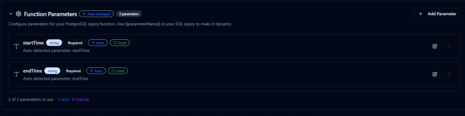
Parameter validation, defaults, and helper text for Siemens S7 functions
Pipeline Integration
Use the Siemens S7 connection functions you configure here as nodes inside the Pipeline Designer to coordinate PLC reads and writes with downstream logic. Drag in the read or write node, bind parameters to upstream outputs or constants, and fine-tune retries or operator guidance without leaving the canvas.
For orchestration blueprints that combine S7 with analytics, SQL, or notification steps, review the Connector Nodes page to understand how these nodes fit into broader automation strategies.
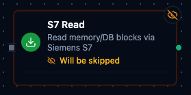
S7 node with connection binding and parameter configuration
Common Use Cases
Production Data Acquisition
Poll Data Blocks for production counts, cycle times, and recipe parameters, then push results to historians or ERP systems.
Supervisory Control
Deliver validated setpoints or mode changes to the PLC in response to business logic, alarms, or operator approvals.
Maintenance Diagnostics
Expose diagnostic bits, buffer alarms, or timer states to maintenance dashboards for rapid troubleshooting.