 Modbus Integration Guide
Communicate with PLCs, drives, meters, and sensors using MaestroHub's Modbus connector. This guide explains connection options, function authoring, pipeline usage, and advanced tuning for reliable operations.
Overview
With the Modbus connector you gain:
- Support for TCP, RTU, and ASCII transports through a single configuration model
- Reusable read/write functions covering coils, discrete inputs, holding registers, and input registers (FC01–FC06, FC15–FC16)
- Rich data type support —
raw,int16,uint16,int32,uint32,float32,int64,uint64,float64,bool,string,hex, andbits - Connection diagnostics including retries, timeouts, health checks, and automatic reconnection
- Quick Add for bulk function creation via table entry or CSV import
Connection Configuration
Creating a Modbus Connection
Navigate to Connections → New Connection → Modbus and configure the following settings. The form is organized into five tabs: Connection, Transport, Advanced, Functions, and Health.
1. Profile Information
| Field | Default | Description |
|---|---|---|
| Profile Name | — | A descriptive name for this connection profile (required, max 100 characters). Must be unique across all connections. |
| Description | — | Optional description for this Modbus connection |
2. Connection Mode Settings
| Field | Default | Description |
|---|---|---|
| Transport Mode | tcp | Modbus communication protocol: TCP (Ethernet), RTU (Serial Binary), or ASCII (Serial Text) — required |
| Unit ID | 1 | Modbus slave unit identifier (0–247) |
3. TCP Transport Settings
(Only displayed when Transport Mode = TCP)
| Field | Default | Description |
|---|---|---|
| IP Address:Port | localhost:502 | Target device address in host:port format (standard Modbus TCP port is 502) — required |
| Connect Timeout (ms) | 3000 | Maximum time to wait for TCP connection (1,000–60,000 ms) |
| Enable TCP Keep-Alive | true | Send periodic keep-alive probes to detect connection failures |
| Keep Alive Period (ms) | 30000 | TCP keep-alive probe interval (1,000–1,800,000 ms) |
4. Serial Transport Settings
(Only displayed when Transport Mode = RTU or ASCII)
| Field | Default (RTU) | Default (ASCII) | Description |
|---|---|---|---|
| Serial Device | /dev/ttyUSB0 | /dev/ttyUSB0 | Serial port device path (e.g., /dev/ttyUSB0 on Linux, COM3 on Windows) — required |
| Baud Rate | 9600 | 9600 | Serial communication speed (1200/2400/4800/9600/19200/38400/57600/115200) — required |
| Data Bits | 8 | 7 | Number of data bits per character (7 or 8) — required |
| Parity | N (None) | E (Even) | Error detection method (N=None / E=Even / O=Odd) — required |
| Stop Bits | 1 | 1 | Number of stop bits per character (1 or 2) — required |
| RS-485 Mode | false | false | Enable RS-485 transceiver mode (direction control) |
5. Advanced Settings
The Advanced tab contains timeout, retry, and serial timing options:
5a. Timeout & Retry Configuration
| Field | Default | Description |
|---|---|---|
| Request Timeout (ms) | 5000 | Maximum time to wait for a Modbus response (1,000–60,000 ms) |
| Idle Timeout (ms) | 10000 | Close connection after idle period (0–600,000 ms; 0 = never) |
| Retry Count | 2 | Number of retries on communication failure (0–10) |
| Retry Delay (ms) | 500 | Delay between retry attempts (100–60,000 ms) |
5b. Serial Advanced Options
(Only displayed when Transport Mode = RTU or ASCII)
| Field | Default | Description |
|---|---|---|
| Inter-Frame Delay (ms) | 0 | Silent interval between frames (0–10,000 ms; 0 = automatic per Modbus spec) |
| Inter-Character Delay (ms) | 0 | Delay between characters (0–1,000 ms; 0 = automatic) |
| Read Timeout (ms) | 0 | Low-level serial read timeout (0–10,000 ms; 0 = use default) |
5c. Read Group Optimization
The Modbus Read Group node running in parallel execution mode coalesces adjacent register reads into a single broader Modbus request to reduce TCP roundtrips. This setting lets you tune how aggressively that batching happens for this specific connection.
| Field | Default | Description |
|---|---|---|
| Coalesce Max Register Gap | (empty — uses global default 0) | Maximum number of unmapped registers the executor may request between two adjacent functions in order to merge them into one Modbus request (0–125). Higher values reduce roundtrips but require those in-between registers to be mapped on the slave. |
How it works
Suppose you have three Read Holding Register functions at addresses 100, 102, and 108, each reading 2 registers. With coalesceMaxGap = 0 they are merged only when strictly adjacent (100+102 → one request) and 108 becomes a separate request. With coalesceMaxGap = 6 all three merge into a single ReadHolding(100, 10) request — but the executor now also asks the slave for registers 104–107, which must be mapped on that device.
Choosing a value
0(default, safe) — The executor never requests a register you didn't configure. Works on every Modbus slave, including those with sparse register maps. Still reduces requests significantly when functions cover contiguous addresses.1–4— Tolerates small alignment padding between measurement groups. Works on most well-documented industrial meters and PLCs.5–10— Aggressive batching. Recommended only when you have verified from the device's register map documentation that all registers in the gap range are addressable (even if reserved/zero).- Higher values — Use only with intimate knowledge of the device's address space. The Modbus protocol limit is 125 registers per request.
Symptom of a value that's too high
If you see every function in a Read Group return modbus: exception '2' (illegal data address) — including functions whose individual read works fine when tested in isolation — your gap is exceeding what the slave will accept. Modbus slaves reject the entire coalesced read when any register in the requested range is unmapped, so a single hole anywhere in the merged span fails every function in that batch. Lower this setting (or set it to 0) until the errors disappear.
6. Health Check Configuration
Health check is always enabled for Modbus connections to ensure reliable device communication.
6a. Basic Health Check Settings
| Field | Default | Description |
|---|---|---|
| Health Check Method | status | Health check type: Status (connection test only) or Read (perform an actual device read) |
| Retry Count | 1 | Number of retries for failed health checks (0–10) |
| Check Interval (ms) | 30000 | How often to perform health checks (1,000–86,400,000 ms; 1 s – 24 h) |
6b. Read Method Fields
(Only displayed when Health Check Method = Read)
| Field | Default | Description |
|---|---|---|
| Register Type | holding | Type of register/coil to read: coil (FC01), discrete (FC02), holding (FC03), or input (FC04) — required |
| Address | 0 | Starting address to read (0–65,535) — required |
| Quantity | 1 | Number of registers/coils to read (1–2,000 for coils/discrete; 1–125 for registers) — required |
| Timeout (ms) | 3000 | Health check request timeout (1,000–60,000 ms) — required |
| Expected Value | — | Optional expected value for validation (0–65,535; leave empty to skip) |
7. Connection Labels
| Field | Default | Description |
|---|---|---|
| Labels | — | Key-value pairs to categorize and organize this Modbus connection (max 10 labels) |
Example Labels
environment: production— Deployment environmentline: line-1— Production lineequipment: plc— Equipment typelocation: factory-floor— Physical location
- Health Check is always enabled for Modbus connections to ensure reliable device communication.
- Fields marked as "required" must be filled out before creating or saving the connection.
- TCP and Serial settings are mutually exclusive based on the selected Transport Mode.
- All timeout values are in milliseconds (ms).
- The form includes real-time validation for all required fields.
- ASCII mode defaults to 7 data bits and Even parity per the Modbus ASCII specification.
Function Builder
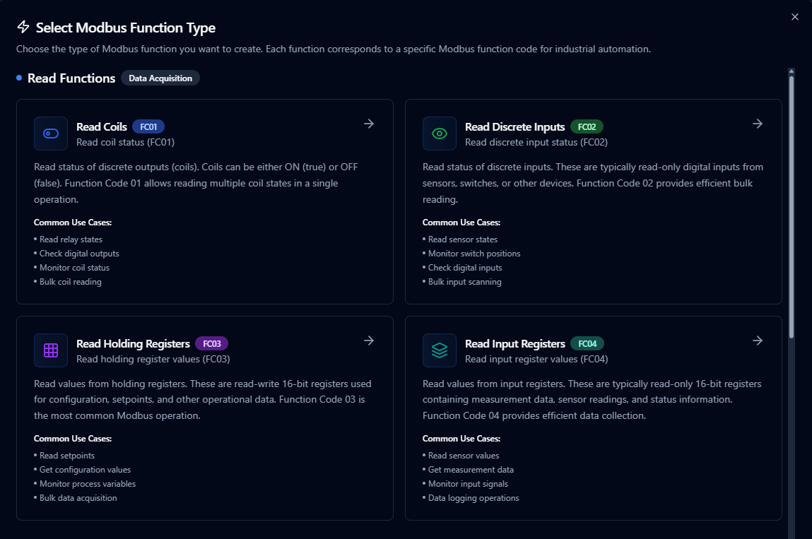
Creating Modbus Functions
After the connection is saved:
- Open the connection and navigate to the Functions tab
- Click New Function to open the function type selection dialog
- Choose a Read function (FC01–FC04) or a Write function (FC05–FC06, FC15–FC16)
- Fill in the Basic tab (name, description, labels) and the Configuration tab (addresses, values)
- Use the Test button to validate the function before saving
Each function has two configuration tabs:
- Basic — Function name (required, max 100 characters, must be unique within the connection), optional description, and labels
- Configuration — Function-specific parameters (address, quantity, values, data type)
Configure Modbus read operations with addressing, scaling, and output aliases

Author Modbus write functions with validation and safety checks
Quick Add: Bulk Function Creation
For scenarios where you need to create multiple Modbus functions at once, the Quick Add feature streamlines the process by allowing you to define many functions in a single operation.
When to Use Quick Add
- Setting up a new Modbus connection with dozens of tags to monitor
- Migrating existing tag lists from spreadsheets or documentation
- Standardizing function creation across multiple similar devices
- Quickly prototyping data collection without creating functions one by one
How to Use Quick Add
- Navigate to your Modbus connection in Connections
- Click Quick Add Functions button
- Choose your input method:
- Table Entry: Add rows directly in the interface
- CSV Import: Upload a CSV file with function definitions
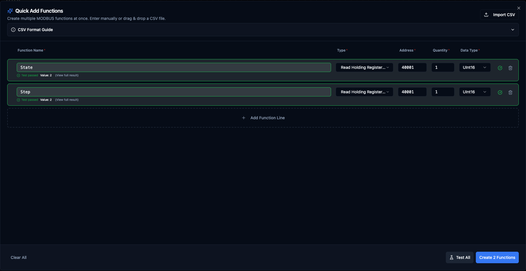
Quick Add Functions dialog with table entry and CSV import options
Table Columns
The Quick Add table enables and disables columns based on the function code so you only fill in the fields that function actually uses.
| Column | Applies to | Description | Example |
|---|---|---|---|
| Function Name | All FCs | Unique name for the function | Temperature_Sensor_1 |
| Type | All FCs | Modbus function code | Read Holding Registers (FC03) |
| Address | All FCs | Starting register/coil address (0–65,535) | 40001 |
| Quantity | Reads only | Number of registers/coils to read. Disabled for writes (single = 1 implicit, multi = derived from the Values cell). | 1 |
| Data Type | Holding/Input register reads only | Value interpretation. Disabled (and ignored) for coil/discrete reads and all writes. | float32, uint16, int32 |
| Value | Single writes (FC05, FC06) | The value to write. Coils accept true/false/on/off/yes/no/1/0; registers accept decimal 0–65535 or 0xHEX. | true, 1500, 0x00FF |
| Values | Multi writes (FC15, FC16) | Comma- or whitespace-separated list of values. Same per-value rules as the Value column. | true,false,true,true, 100,200,300 |
| Labels | Optional, all FCs | Per-function tags for filtering and grouping. Click the Labels button to edit; the badge shows the current count. In CSV use key=value;key=value. Up to 10 labels per function. | area=motors;team=automation |
Supported Function Types in Quick Add
- Read Coils (FC01)
- Read Discrete Inputs (FC02)
- Read Holding Registers (FC03)
- Read Input Registers (FC04)
- Write Single Coil (FC05)
- Write Single Register (FC06)
- Write Multiple Coils (FC15)
- Write Multiple Registers (FC16)
CSV Import Format
The CSV mirrors the table columns. Leave a cell empty when the function code doesn't use it (e.g. no dataType for coil reads, no value for read functions). Quote any cell that contains commas — used for the multi-write values column.
The labels column is optional. Pairs are separated by ; and each pair uses key=value. The first = per pair is the delimiter so values can contain =. Whitespace around = and ; is tolerated. Label values cannot contain a literal ; in CSV — use the popover editor when you need that.
name,functionType,address,quantity,dataType,value,values,labels
Temperature,read.holdingRegisters,40001,1,float32,,,area=process;env=prod
FlowRate,read.holdingRegisters,40010,2,uint32,,,area=process
RawBlock,read.holdingRegisters,40100,8,raw,,,
SetpointReg,read.inputRegisters,30005,1,uint16,,,
RelayBank,read.coils,0,8,,,,area=relays
DoorSensors,read.discreteInputs,10000,16,,,,team=facilities
EnableRelay,write.singleCoil,5,,,true,,team=automation
SetSpeed,write.singleRegister,40020,,,1500,,team=automation;priority=high
StartupRelays,write.multipleCoils,10,,,,"true,false,true,true",team=automation
ParamBlock,write.multipleRegisters,40050,,,,"100,200,300,400",team=automation
Validation Rules
- Function names must be unique within the connection.
- Addresses must be in range 0–65,535.
- Read operations: quantity must be at least 1, and within the per-FC cap enforced by the backend:
- Read Coils / Read Discrete Inputs: 2,000 max
- Read Holding Registers / Read Input Registers: 125 max (further constrained by data type width — see below)
- Multi-byte data types use multiple registers: total registers (quantity × data type register count) cannot exceed 125 for register reads.
- Example: 50 ×
float32(2 regs each) = 100 registers ✓, 32 ×uint64(4 regs each) = 128 > 125 ✗
- Example: 50 ×
- Write operations:
- Single writes (FC05, FC06): Value is required.
- Write Multiple Coils (FC15): at least 1 and at most 1,968 boolean values.
- Write Multiple Registers (FC16): at least 1 and at most 123 uint16 values.
Best Practices
- Use descriptive function names that reflect the physical sensor or control point
- Group related functions together using consistent naming (e.g.,
Tank1_Temperature,Tank1_Pressure) - Validate your CSV file with a small batch before importing hundreds of functions
- Consider data type register counts when planning bulk reads to stay within the 125 register limit
Data Types
Modbus register data can be interpreted using the following data types. The data type determines how raw 16-bit register values are converted into meaningful values.
| Data Type | Registers | Description |
|---|---|---|
raw | Variable | No conversion — returns array of raw 16-bit unsigned values |
bool | 1 | Single bit/coil value (true/false) |
int16 | 1 | Signed 16-bit integer (−32,768 to 32,767) |
uint16 | 1 | Unsigned 16-bit integer (0 to 65,535) |
int32 | 2 | Signed 32-bit integer |
uint32 | 2 | Unsigned 32-bit integer |
float32 | 2 | IEEE 754 single-precision floating point |
int64 | 4 | Signed 64-bit integer |
uint64 | 4 | Unsigned 64-bit integer |
float64 | 4 | IEEE 754 double-precision floating point |
string | Variable | ASCII text (2 characters per register, null-terminated) |
hex | Variable | Hexadecimal string representation (e.g., FF00 00A1) |
bits | Variable | Bit array — 16 bits per register, MSB first |
When reading multi-register data types, set the Quantity field to match the register count. For example, reading a float32 value requires a quantity of at least 2 registers, and float64 requires 4.
Read Coils (modbus.read.coils)
Purpose: Read status of discrete outputs (coils) using Function Code 01. Coils can be either ON (true) or OFF (false), allowing reading of multiple coil states in a single operation.
Configuration Fields
| Field | Type | Required | Default | Description |
|---|---|---|---|---|
| Starting Address | Number | Yes | 0 | First coil address to read (0–65,535) |
| Quantity | Number | Yes | 1 | Number of coils to read in sequence (1–2,000) |
Use Cases: Read relay states, check digital outputs, monitor coil status, bulk coil reading
Read Discrete Inputs (modbus.read.discreteInputs)
Purpose: Read status of discrete inputs using Function Code 02. These are typically read-only digital inputs from sensors, switches, or other devices.
Configuration Fields
| Field | Type | Required | Default | Description |
|---|---|---|---|---|
| Starting Address | Number | Yes | 10000 | First discrete input address to read (0–65,535) |
| Quantity | Number | Yes | 8 | Number of discrete inputs to read (1–2,000) |
Use Cases: Read sensor states, monitor switch positions, check digital inputs, bulk input scanning
Read Holding Registers (modbus.read.holdingRegisters)
Purpose: Read values from holding registers using Function Code 03. These are read-write 16-bit registers used for configuration, setpoints, and other operational data. This is the most common Modbus operation.
Configuration Fields
| Field | Type | Required | Default | Description |
|---|---|---|---|---|
| Starting Address | Number | Yes | 40001 | First holding register address to read (0–65,535) |
| Quantity | Number | Yes | 10 | Number of registers to read (1–125) |
| Data Type | Select | No | raw | Data type for value conversion (see Data Types table) |
Use Cases: Read setpoints, get configuration values, monitor process variables, bulk data acquisition
Read Input Registers (modbus.read.inputRegisters)
Purpose: Read values from input registers using Function Code 04. These are typically read-only 16-bit registers containing measurement data, sensor readings, and status information.
Configuration Fields
| Field | Type | Required | Default | Description |
|---|---|---|---|---|
| Starting Address | Number | Yes | 30001 | First input register address to read (0–65,535) |
| Quantity | Number | Yes | 4 | Number of registers to read (1–125) |
| Data Type | Select | No | raw | Data type for value conversion (see Data Types table) |
Use Cases: Read sensor values, get measurement data, monitor input signals, data logging operations
Write Single Coil (modbus.write.singleCoil)
Purpose: Write a single coil (discrete output) to ON or OFF state using Function Code 05. Used for controlling individual relays, digital outputs, or other binary actuators.
Configuration Fields
| Field | Type | Required | Default | Description |
|---|---|---|---|---|
| Coil Address | Number | Yes | 0 | Address of the coil to write (0–65,535) |
| Coil Value | Boolean | Yes | true | State to write to the coil (true = ON, false = OFF). Supports parameter templates. |
Use Cases: Control relay states, set digital outputs, toggle equipment on/off, actuator control
Write Single Register (modbus.write.singleRegister)
Purpose: Write a single 16-bit value to a holding register using Function Code 06. Used for setting configuration values, setpoints, and other control parameters.
Configuration Fields
| Field | Type | Required | Default | Description |
|---|---|---|---|---|
| Register Address | Number | Yes | 40001 | Address of the register to write (0–65,535) |
| Register Value | Number | Yes | 0 | 16-bit value to write (0–65,535). Supports parameter templates. |
Use Cases: Set configuration values, update setpoints, write control parameters, individual register updates
Write Multiple Coils (modbus.write.multipleCoils)
Purpose: Write multiple coils (discrete outputs) in a single operation using Function Code 15. Allows efficient bulk control of relays, digital outputs, or other binary devices.
Configuration Fields
| Field | Type | Required | Default | Description |
|---|---|---|---|---|
| Starting Address | Number | Yes | 0 | First coil address to write (0–65,535) |
| Coil Values | Array | Yes | [true, false] | Array of boolean values for each coil (1–1,968 coils). Supports parameter templates. |
Use Cases: Control multiple relays, set digital output patterns, bulk coil updates, equipment sequences
Write Multiple Registers (modbus.write.multipleRegisters)
Purpose: Write multiple 16-bit values to consecutive holding registers using Function Code 16. Allows efficient bulk updates of configuration data, setpoints, and control parameters.
Configuration Fields
| Field | Type | Required | Default | Description |
|---|---|---|---|---|
| Starting Address | Number | Yes | 40001 | First register address to write (0–65,535) |
| Register Values | Array | Yes | [0, 0] | Array of 16-bit values for consecutive registers (1–123 registers, each 0–65,535). Supports parameter templates. |
Use Cases: Bulk configuration updates, set multiple setpoints, write parameter blocks, data download operations
Using Parameters
Parameter placeholders ((parameterName)) can be used in write function fields (value, values, address) to make functions dynamic at execution time.
| Configuration | Description | Example |
|---|---|---|
| Type | Validate expected value type | number, boolean, array, json |
| Required | Force critical inputs | Required / Optional |
| Default Value | Provide safe fallbacks | false, 250.0 |
| Description | Document purpose | "Start/Stop command flag", "Setpoint in °C" |
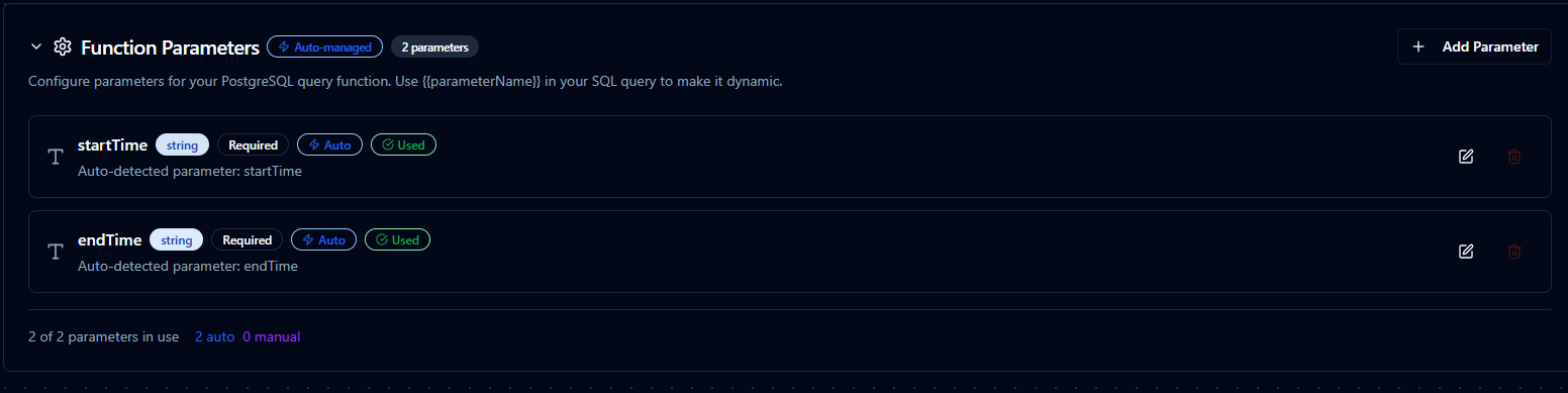
Parameter configuration for Modbus scaling, coercion, and safety notes
Testing Functions
Every Modbus function can be tested before saving using the built-in Test dialog:
- Click the Test button in the function form
- The dialog shows an Execution Overview with the current configuration
- Override any parameter values in the Test Parameters section
- Click Execute Test to run the function against the live device
- View the result in the integrated JSON viewer, including execution duration and timestamp
The test dialog supports two modes:
- Config-only Testing (create mode) — Tests the function configuration before saving
- Function with Overrides (edit mode) — Tests the saved function with current form modifications
Pipeline Integration
Use the Modbus connection functions you define here as nodes inside the Pipeline Designer to synchronize PLC registers with the rest of your pipeline. Drag in the read or write node, bind parameters to upstream outputs or constants, and set retries or guard conditions before issuing commands.
For orchestration strategies that mix Modbus with other data sources, check the Connector Nodes page to see how these nodes slot into larger automation flows.

Modbus read node with connection, function, and parameter bindings
Common Use Cases
Equipment Monitoring
Poll holding and input registers for temperature, flow, vibration, or energy metrics, then forward the data to historians or MQTT topics.
Control and Setpoint Management
Validate operator inputs and write them back to coils or registers to adjust production processes safely.
Data Normalization
Convert raw register values into engineering units, status codes, or structured JSON for downstream analytics using the built-in data type conversions (float32, int32, etc.).
Troubleshooting
Connection Issues
| Symptom | Possible Cause | Solution |
|---|---|---|
| Connection timeout | Device not reachable | Verify network connectivity, IP address, and port. Standard Modbus TCP port is 502. |
| Invalid address format | Malformed host:port | Ensure address is in host:port format (e.g., 192.168.1.10:502). Port must be 1–65,535. |
| Serial port error | Wrong device path | Verify the serial device path (/dev/ttyUSB0, COM3, etc.) and that the port is not in use. |
| Unit ID mismatch | Wrong slave address | Confirm the Unit ID matches the device's configured slave address (0–247). |
| Health check fails | Device unresponsive | Check the health check method and register settings. Try switching to Status method first. |
Function Issues
| Symptom | Possible Cause | Solution |
|---|---|---|
| Illegal function error | Unsupported function code | Verify the device supports the requested function code (e.g., not all devices support FC15/FC16). |
| Illegal data address | Address out of range | Check that the starting address and quantity don't exceed the device's address space. |
| Read Group: every function returns "illegal data address" in parallel mode but works in sequential mode | Coalescing is including unmapped registers in the merged request | Lower Coalesce Max Register Gap on the connection (Section 5c) to a value the slave accepts, or set it to 0 for safe per-function reads. |
| Incorrect values | Wrong data type | Ensure the data type matches the device's register format (e.g., float32 for IEEE 754 values). |
| Register limit exceeded | Too many registers | Reduce quantity — maximum is 125 for register reads and 2,000 for coil/discrete reads. |
| Timeout on write | Device busy | Increase the request timeout or add retry logic. Check if the device is in a protected mode. |
Use the Test button in the Function Builder to validate your configuration before using it in pipelines. The test dialog lets you override parameters for one-off operations and displays the full response with execution timing.